
Multiplexers and demultiplexers are digital circuits used in digital systems for data transmission, selection, and routing. A multiplexer, also known as a “MUX” is a combinational circuit that selects one of several input signals and transmits it to a single output line based on a set of selection inputs. A demultiplexer, also known as a “DEMUX” is a combinational circuit that receives a single input signal and routes it to one of several output lines based on a set of selection inputs.
Multiplexers:
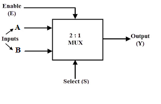
A multiplexer has n input lines and a set of selection inputs, typically referred to as “selection lines,” which determine which of the input lines is transmitted to the output line. The number of selection lines determines the number of input lines that can be selected. For example, a 2-to-1 multiplexer has two input lines and one selection line, while a 4-to-1 multiplexer has four input lines and two selection lines.
The truth table for a 2-to-1 multiplexer is as follows:
| Selection | Input A | Input B | Output |
|---|---|---|---|
| 0 | 0 | 0 | 0 |
| 0 | 0 | 1 | 0 |
| 0 | 1 | 0 | 1 |
| 0 | 1 | 1 | 1 |
As can be seen from the truth table, when the selection input is 0, input A is transmitted to the output, while when the selection input is 1, input B is transmitted to the output.

Demultiplexers:
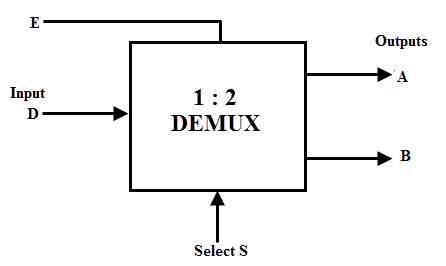
A demultiplexer has a single input line and a set of selection inputs, typically referred to as “selection lines,” which determine which of the output lines the input signal is routed to. The number of selection lines determines the number of output lines that can be selected. For example, a 1-to-2 demultiplexer has one input line and two output lines, while a 1-to-4 demultiplexer has one input line and four output lines.
The truth table for a 1-to-2 demultiplexer is as follows:
| Selection | Input | Output A | Output B |
|---|---|---|---|
| 0 | 0 | 0 | 0 |
| 0 | 1 | 1 | 0 |
| 1 | 0 | 0 | 0 |
| 1 | 1 | 0 | 1 |
As can be seen from the truth table, when the selection input is 0, the input signal is routed to output A, while when the selection input is 1, the input signal is routed to output B.

Differences between a MUX and a DEMUX:
| Feature | Multiplexer (MUX) | Demultiplexer (DEMUX) |
|---|---|---|
| Function | Selects one of several input signals and transmits it to a single output line | Receives a single input signal and routes it to one of several output lines |
| Input Lines | Multiple input lines | One input line |
| Output Lines | One output line | Multiple output lines |
| Selection Lines | The number of selection lines is equal to the logarithm base 2 of the number of input lines | The number of selection lines is equal to the logarithm base 2 of the number of output lines |
| Control | Selection lines control which input signal is transmitted | Selection lines control which output line the input signal is routed to |
| Application | Used in data communication systems where multiple signals need to be transmitted over a single transmission line | Used in memory systems where a single memory block is accessed by multiple processors |
Hmm it seems like your site ate my first comment (it was extremely long) so I guess I’ll just
sum it up what I submitted and say, I’m thoroughly enjoying your blog.
I too am an aspiring blog writer but I’m still new to
everything. Do you have any recommendations for first-time blog writers?
I’d really appreciate it.
Hi i am kavin, its my first occasion to commenting
anywhere, when i read this post i thought i could also create comment due to
this good post.
Thanks a bunch for sharing this with all folks you actually recognise what you are speaking about!
Bookmarked. Kindly additionally discuss with my website =).
We could have a link change contract among us
I appreciate, result in I found just what I was taking a look for.
You have ended my four day lengthy hunt! God Bless you man. Have a great day.
Bye
Love the site– very user friendly and lots to see! acquisto di clonidine in Roma
This piece of writing will assist the internet users for setting up new
blog or even a weblog from start to end.
thanx
Hi there friends, its enormous post concerning educationand completely explained, keep it up all
the time.
I think the admin of this web site is really working hard in support of his website, because here every information is quality based data.
Hey very interesting blog!
Good day! This is my 1st comment here so I just wanted to give a quick shout out and say I genuinely enjoy reading through
your articles. Can you suggest any other blogs/websites/forums that go over the same
topics? Thank you so much!